
High-quality products must function reliably even under unexpected conditions and under the influence of noise factors. Such noise factors occur repeatedly during a product's life cycle and often cannot be controlled. Helbling has developed and implemented methods to incorporate this aspect early in the product development stage. The principles of robust design aim to minimize the influence of noise factors through appropriate design. This significantly reduces performance losses during the production and utilization phase of a product.
Robust is defined as insensitive or not easily disturbed. In the case of products, this means that noise factors have little influence on function and quality. A robust product not only works well under ideal conditions in the laboratory, but also in the real world. Robust design is relevant to high-tech systems in unusual environments such as satellites in space and particularly for consumer goods, where mass production meets complexity. Helbling has already successfully completed projects with robust design in these areas in which experts have developed and applied specific processes.
System design and parameter design make significant contributions to robust design early on in the development process. The specifications of individual parts are subsequently defined in the tolerance design. These specifications describe the permissible deviations from the ideal properties and are crucial for the flawless functioning of the end product. The challenge is to harmonize these specifications so that they meet the following criteria:
- The specifications should be traceable to higher-level requirements.
- They must be reliably achievable with the selected manufacturing processes.
- Any combination of individual parts must result in a functioning system.
Reducing variance with parameter design
Achieving low variance is crucial for robust design. This can be achieved by selecting areas with flatter transfer functions in parameter design. An example of two springs in Figure 1 illustrates the effects of changes in length on the variance of force and shows the importance of sensitivity in practice.

Establishing design clarity
Real components always deviate from ideal CAD models. Tolerance definitions from the developer are crucial for function, as they describe permissible variations from the ideal shape. Nowadays, this design intent can be stored directly in the 3D CAD model using model-based definition (MBD).
In addition to tolerances, the actual geometry also provides clarity. For example, the length of the connection in Figure 2 is decisive when it comes to the number of degrees of freedom that are restricted by this interface.
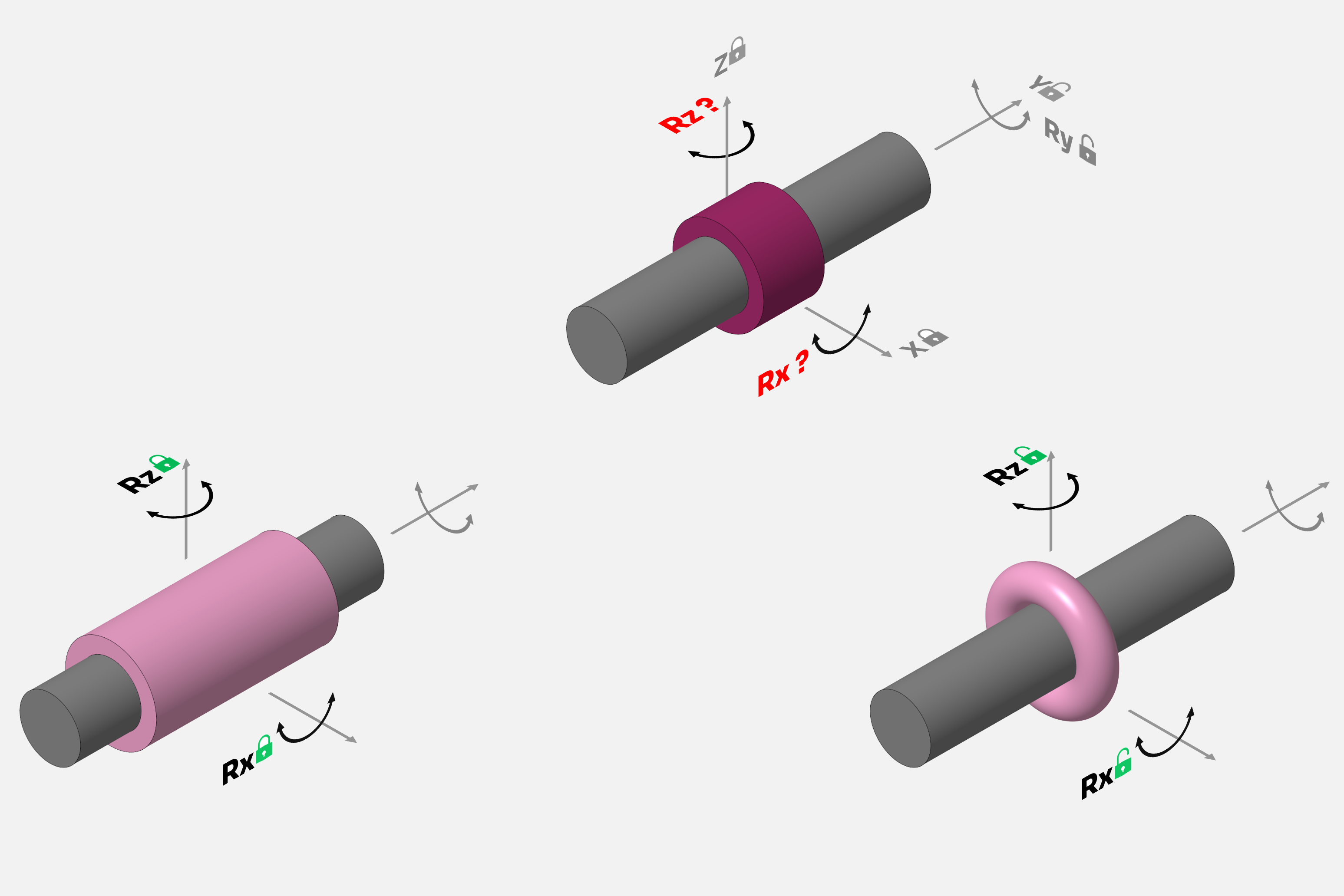
Image: Helbling
Ideally, degrees of freedom should be restricted exactly once within an assembly to avoid indeterminate states. Systematic analysis using the Grübler equation helps to identify over-constraints. Over-constraints can be accepted in some cases, but often require tighter tolerances so that a kinematic chain does not suddenly jam. This analysis also enables the comparison of different kinematic chains at a conceptual level.
Generating the tolerances of individual parts and assemblies directly in the 3D model
A complete description of permissible deviations of components according to ISO GPS is of great importance. Size, shape, position, and orientation should be fully specified. A 3D tolerance simulation is used to check the critical functions. If the required tolerances cannot be achieved with the selected manufacturing processes, corrective measures must be defined. Proven options then include shortening the tolerance chain or an additional manufacturing step with higher accuracy for a large contributor.
With the latest tools, the tolerance model becomes part of the assembly so tolerances can be transferred directly from the CAD model using model-based definition and the model is also saved in the assembly. Manual transfer is completely eliminated.
Simplifying the process with 3D verification tools
3D scanning and verification enable produced parts to be fully captured and checked against the specification. With the aid of model-based definition, the tolerances from a CAD model can also be accessed in this work step, making traditional 2D drawings superfluous. This change affects many downstream processes and is only gaining momentum slowly in the industry. Helbling has been following this change for several years, gaining experience on projects and precisely analyzing sample parts in this way.
Summary: Robust design enables reliability and efficiency
Integrating various methods and tools such as design clarity and 3D tolerance simulation allows robust products to be developed efficiently. By consistently applying these methods, Helbling has proven that the final product is not only convincing in use but also in production. This approach also enables more efficient collaboration with manufacturers and OEMs.
Authors: Martin Ziegler, Stefan Käser
Main Image: Volkswagen
References
Grübler, M. (1917). Getriebelehre. Berlin: Julius Springer. Von https://hdl.handle.net/1813/58336 abgerufen
Taguchi, G. (1993). Taguchi on Robust Technology Development. New York.